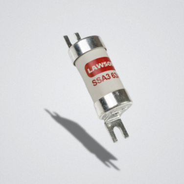
If you have ever opened a panel schedule or a BS 88 catalogue and found yourself staring at a column of gG and gM designations side by side, you are not alone. The two utilisation categories look similar, carry the same voltage and current ratings, and are physically interchangeable in most fuse-bases — yet specifying the wrong one can cause repeated nuisance tripping on motor circuits or leave cables underprotected.
This guide explains exactly what separates gG from gM, when each is the right choice, and how to apply the relevant IEC 60269 and BS 88 standards when sizing fuses for real-world installations.
What is a utilisation category?
Under IEC 60269-1 and BS 88, every low voltage HRC fuse-link carries a two-letter utilisation category code. The first letter describes the breaking range:
- g — general purpose, full-range fuse. Can interrupt any current from the minimum fusing current up to the rated breaking capacity.
- a — back-up fuse. Only interrupts currents above a defined threshold; requires a supplementary device for lower overcurrents.
The second letter describes the application:
- G — general circuit protection (cables, distribution, mixed loads)
- M — motor circuit protection
So gG means a full-range general purpose fuse, and gM means a full-range motor protection fuse.
How gG and gM fuses differ
Both gG and gM are full-range fuses compliant with IEC 60269-1. Both protect against overloads and short circuits. The key difference is in their time-current characteristic — the curve that defines how quickly a fuse operates at any given overcurrent multiple.
The gG time-current characteristic
A gG fuse follows a relatively steep time-current curve optimised for cable protection. At two to three times its rated current it operates within a defined time, providing accurate overload protection. This precision is exactly what you want when protecting a distribution cable: you need the fuse to clear a sustained overload before insulation is damaged, but not so slowly that it tolerates excessive heating.
The gM time-current characteristic
A gM fuse has two current ratings: the rated current In (the marking on the fuse body) and the rated motor current Im (the continuous current it is actually designed to carry). In most catalogue entries Im = In, but the fuse’s time-current curve is deliberately shifted to be slower in the overload region compared to a gG of the same marking.
This slower overload response is what allows a gM fuse to survive the inrush current that occurs every time a motor starts. A direct-on-line (DOL) motor can draw five to eight times its full-load amps for several seconds at start-up. A standard gG fuse rated to the motor’s full-load current would see this inrush as an overload and clear — the exact nuisance tripping problem that gM was designed to prevent.
Key insight: gM fuses are not slower overall — they are selectively slower in the overload region to ride through motor inrush, while retaining rapid short-circuit response at high fault currents.
Side-by-side comparison
| Property | gG | gM | gG Best For | gM Best For |
|---|---|---|---|---|
| Full name | General purpose, full-range | Motor circuit, full-range | — | — |
| Breaking range | Full range (overload + S/C) | Full range (overload + S/C) | — | — |
| Time-current curve | Standard gG curve | Shifted — slower at overload | — | — |
| Overload tolerance | Standard | Higher — tolerates motor inrush | — | — |
| Typical application | Cable & general circuit protection | Motor starters & DOL circuits | Distribution boards, cables | Motor branch circuits |
| Standard | IEC 60269-1 / BS 88 | IEC 60269-1 / BS 88 | — | — |
| Cost | Lower | Slightly higher | Budget-sensitive installs | Motor-heavy plant |
Note: gG and gM fuses are generally interchangeable in the same fuse-base (same size, voltage rating, and BS 88 / IEC 60269 compliance). The difference is in the characteristic, not the form factor.
The motor starting problem in detail
To understand why gM exists, consider a 15 kW DOL motor on a 400 V supply:
- Full-load current (FLA): approximately 30 A
- Starting inrush: typically 180–240 A for 2–5 seconds
- A gG fuse rated at 32 A would see 180 A as roughly 5.6 × In
- At 5.6 × In, a 32 A gG fuse typically clears in 1–10 seconds depending on the specific characteristic
- Depending on the motor’s actual start time, a marginal gG fuse can clear during starting — causing nuisance trips on every motor start
The traditional workaround was to oversize the gG fuse — selecting a 50 A or 63 A fuse for a 30 A motor. This stops the tripping but sacrifices overload protection: the fuse no longer provides meaningful protection for the cable feeding the motor starter.
A correctly sized gM fuse eliminates this compromise. Sized to the motor’s FLA, it rides through the inrush without tripping while still protecting the circuit cable against genuine overloads.
Sizing gM fuses to BS 88 and IEC 60269
The selection process for gM fuses is straightforward when following the standard:
- Identify the motor’s full-load current from the nameplate or the motor data sheet.
- Select a gM fuse with In equal to or slightly above the full-load current. Most manufacturers publish application tables aligning fuse ratings to standard motor sizes.
- Verify that the fuse’s I²t let-through value is compatible with the cable’s rated withstand. For motor branch circuits, cable sizing must also account for BS 7671 / IEC 60364 requirements.
- Check coordination with the upstream device. The motor branch circuit gM fuse must coordinate with the main distribution board’s gG fuse so that only the motor branch circuit fuse clears on a fault.
For larger motors, or where the start time is unusually long (e.g. high-inertia loads, variable-speed pump restarts), consult the fuse manufacturer’s application guidance. Lawson Fuses provides detailed time-current characteristic curves and application data for all gM products.
When gG is the right choice
gG remains the correct specification in the majority of general circuit applications:
- Distribution cable protection in switchgear and distribution boards
- Transformer primary protection (the brief transformer inrush is handled by gG characteristics)
- Circuits supplying mixed loads where no single motor dominates
- Lighting circuits
- Busbar protection in low voltage switchgear
- Any application where the load profile does not include significant inrush
gG’s tighter overload characteristic actually makes it more protective in these contexts. Replacing gG with gM on a distribution board main fuse, for example, would reduce overload protection accuracy without offering any benefit.
Quick decision guide
| Motor Rating | Direct-on-line Start (3x FLC for 10 sec) Fuse-Link Rating (Amperes) |
Assisted Start (3.5x FLC for 20 sec) Fuse-Link Rating (Amperes) |
|||
|---|---|---|---|---|---|
| KW | HP | FLC | gG | gM | gM |
| 0.75 | 1 | 2 | 6 | – | 4 |
| 1.1 | 1.5 | 2.5 | 10 | – | 6 |
| 1.5 | 2 | 3 | 10 | – | 6 |
| 2.2 | 3 | 5 | 16 | – | 10 |
| 3 | 4 | 6.5 | 20 | – | 16 |
| 4 | 5.5 | 8 | 25 | – | 16 |
| 5.5 | 7.5 | 11 | 32 | 20M25 | 20 |
| 7.5 | 10 | 15 | 40 | 32M40 | 25 |
| 10 | 13.5 | 19 | 50 | 32M50 | 32 |
| 12.5 | 17 | 21 | 63 | 32M63 | 40 |
| 15 | 20 | 28 | 63 | 32M63 | 40 |
| 18.5 | 25 | 35 | 80 | 63M80 | 50 |
| 22 | 30 | 41 | 80 | 63M100 | 63 |
| 25 | 33 | 46 | 100 | 63M100 | 63 |
| 30 | 40 | 55 | 125 | 100M160 | 80 |
| 37 | 50 | 69 | 160 | 100M160 | 80 |
| 45 | 60 | 83 | 200 | 100M200 | 100 |
| 55 | 75 | 100 | 200 | 100M200 | 125 |
| 60 | 80 | 110 | 250 | 200M250 | 160 |
| 75 | 100 | 135 | 250 | 200M250 | 160 |
| 90 | 120 | 160 | 315 | 200M315 | 200 |
| 93 | 125 | 165 | 355* | – | 200 |
| 110 | 150 | 200 | 400 | 315M400* | 250 |
| 132 | 175 | 240 | 400 | 315M400* | – |
| 150 | 200 | 280* | 450* | – | 315M400* |
| 160 | 215 | 280 | 500 | 400M500* | 355* |
| 170 | 230 | 300 | 500 | 400M500* | 355* |
| 185 | – | – | 500 | 4M500* | – |
| 200 | 270 | 350 | 630 | – | 400 |
| 220 | 300 | 385 | 630* | – | 400 |
| 250 | 335 | 435 | 710* | – | 500 |
| 260 | 350 | 450 | 750* | – | 560 |
| 300 | 400 | 500 | 800 | – | 630 |
| Direct-on-line Start (3x FLC for 10 sec) Fuse-Link Rating (Amperes) |
Assisted Start (3.5x FLC for 20 sec) Fuse-Link Rating (Amperes) |
||||
|---|---|---|---|---|---|
| gG | gM | Maximum Motor FLC |
gG | gM | Maximum Motor FLC |
| 2 | – | 0.6 | 2 | – | 0.6 |
| 4 | – | 1.3 | 4 | – | 1.3 |
| 6 | – | 2 | 6 | – | 2 |
| 10 | – | 4.1 | 10 | – | 4.1 |
| 16 | – | 6 | 16 | – | 6 |
| 20 | – | 7.6 | 20 | – | 7.6 |
| 25 | 20M25 | 13 | 25 | 20M25 | 13 |
| 32 | 20M32 | 18 | 32 | 20M32 | 18 |
| 40 | 32M50 | 26 | 40 | 32M50 | 26 |
| 50 | 32M63 | 36 | 50 | 32M63 | 36 |
| 63 | 32M63 | 40 | 63 | 32M63 | 40 |
| 80 | 63M80 | 40 | 80 | 63M80 | 40 |
| 80 | 65M100 | 61 | 80 | 65M100 | 61 |
| 100 | 65M100 | 61 | 100 | 65M100 | 61 |
| 125 | 100M125 | 82 | 125 | 100M125 | 82 |
| 160 | 100M160 | 110 | 160 | 100M160 | 110 |
| 200 | 200M250 | 150 | 200 | 200M250 | 150 |
| 200 | 200M315 | 170 | 200 | 200M315 | 170 |
| 250 | 315M400* | 240 | 250 | 315M400* | 240 |
| 315 | 315M400* | 280 | 315 | 315M400* | 280 |
| 355* | 400M500* | 310 | 355* | 400M500* | 310 |
| 450* | 400M500* | 350 | 450* | 400M500* | 350 |
| 500 | – | 380 | 500 | – | 380 |
| 560* | – | 420 | 560* | – | 420 |
| 630* | – | 450 | 630* | – | 450 |
| 670* | – | 460 | 670* | – | 460 |
| 710* | – | 480 | 710* | – | 480 |
| 750 | – | 510 | 750 | – | 510 |
| 800 | – | 510 | 800 | – | 510 |
| Assisted Start | Maximum Motor FLC |
|
|---|---|---|
| (3.5x FLC for 20 sec) Fuse-Link Rating (Amperes) |
||
| “gG” | “gM” | Maximum Motor FLC |
| 2 | – | 1.3 |
| 4 | – | 2 |
| 6 | – | 3 |
| 10 | – | 6.4 |
| 16 | – | 9 |
| 20 | – | 12 |
| 25 | 20M25 | 19 |
| 32 | 20M32 | 24 |
| 40 | 32M40 | 31 |
| 50 | 32M50 | 46 |
| 63 | 32M63 | 51 |
| 80 | – | 69 |
| 100 | – | 94 |
| 100 | – | 110 |
| 125 | – | 150 |
| 160 | – | 180 |
| 200 | – | 210 |
| 250 | – | 230 |
| 315 | – | 250 |
| 355 | – | 310 |
| 400M500* | – | 340 |
| 450* | 400M500* | 380 |
| 500 | – | 430 |
| 560* | – | 460 |
| 630* | – | 500 |
| 670* | – | 530 |
| 710* | – | 550 |
| 750* | – | 570 |
| 800 | – | 600 |
A note on gG/gM marking and interchangeability
Because gG and gM fuses of the same current rating share the same physical dimensions and fuse-base compatibility, it is possible to install one where the other is specified. Do not rely on interchangeability as a shortcut. Installing a gG fuse in a motor circuit that was designed for gM will likely result in nuisance tripping. Installing a gM in a general distribution circuit that was designed for gG will provide slightly less overload protection accuracy.
Always match the utilisation category to the application. When replacing fuses in an existing installation, check the panel schedule or the original design documentation for the specified category before substituting.
Summary
Both gG and gM are full-range HRC fuse-links compliant with IEC 60269 and BS 88. The fundamental difference is in the time-current characteristic:
- gG: standard overload response — precise, cost-effective, and correct for general circuit and cable protection.
- gM: extended overload tolerance — designed to ride through motor inrush without nuisance tripping, while retaining full short-circuit protection.
Specify gG as the default for distribution and general circuits. Specify gM for motor branch circuits, sized to the motor’s full-load current. When in doubt, consult the application data in Lawson Fuses’ technical documentation or speak to our technical team.
About Lawson Fuses
Lawson Fuses has specialised in the design, development and manufacturing of low voltage HRC fuse-links and fuse-holders since 1938. Our products comply with IEC 60269 and BS 88 and are ASTA certified and ISO 9001 accredited. For datasheets, Zs values, application guidance, and trade pricing, visit www.lawsonfuses.com or call 01661 823 232.