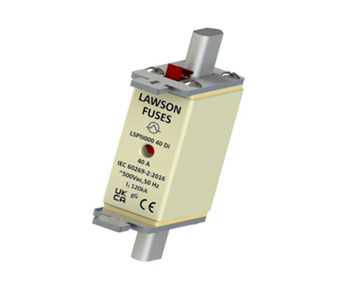
Of all the parameters printed on a fuse-link, the rated current gets the most attention. It sits on the label in large figures, it drives the selection process, and it is the first thing an engineer or electrician checks when replacing a fuse. The breaking capacity, by contrast, is often treated as a footnote — a number on the datasheet that is rarely questioned.
That assumption is dangerous. A fuse installed in a circuit whose prospective fault current exceeds the fuse’s breaking capacity will not protect the installation. It will fail violently, potentially rupturing, sustaining an arc, and causing a fire or serious injury. Understanding what breaking capacity means, how to determine the prospective fault current at any point in a system, and how to read a fuse datasheet correctly is fundamental to safe electrical design.
What breaking capacity means
Breaking capacity (also called interrupting rating or rated short-circuit capacity) is the maximum fault current that a fuse can safely interrupt at its rated voltage. It is expressed in kiloamperes (kA) rms symmetrical for AC systems, or kA for DC systems.
When a fault occurs in an electrical system, the current that flows is limited only by the impedance of the source and the circuit conductors between the source and the fault. Close to a large transformer or a main LV distribution board, that impedance is very low — and the resulting fault current can be extremely high.
The fuse must interrupt this current without:
- Sustaining an arc that continues to conduct after the element melts
- Rupturing the cartridge body and ejecting molten material
- Causing flashover to adjacent phases or earthed metalwork
- Damaging the fuse-holder, fuse-base, or surrounding switchgear
An HRC (High Rupturing Capacity) fuse is specifically designed to do all of this safely at fault currents that would destroy a rewirable or semi-enclosed fuse. The silica sand filling, the carefully profiled element, and the ceramic or high-strength glass-fibre body all contribute to its ability to interrupt very high fault currents without catastrophic failure.
The ‘HRC’ in HRC fuse-link stands for High Rupturing Capacity — a direct reference to this core capability. It is the defining characteristic that separates industrial HRC fuse-links from the rewirable and semi-enclosed fuses used in legacy domestic systems.
Prospective fault current: what it is and how to find it
Definition
The prospective fault current (PFC) — also called the prospective short-circuit current (PSCC) — is the current that would flow if a zero-impedance fault (a bolted short circuit) were applied at a given point in the system. It assumes the worst case: no arc resistance, no contact resistance, and the fault applied at the moment of maximum voltage (the AC voltage peak).
The PFC varies throughout the system. It is highest at the supply terminals and reduces with distance as cable impedance increases. Every fuse in the system must have a breaking capacity equal to or greater than the PFC at the point where it is installed.
How to calculate PFC
The prospective fault current at any point in a system is calculated from:
Isc = U₀ / Ze
Where U₀ = nominal phase-to-earth voltage (230 V in a UK 400 V TN system) and Ze = total earth fault loop impedance at the point of measurement (in ohms)
For three-phase fault current (the higher value used for breaking capacity verification):
Isc(3-phase) = U / (√3 × Zs)
Where U = line-to-line voltage (400 V) and Zs = total positive-sequence impedance from source to fault point
In practice, engineers use one of three methods to determine PFC:
- Calculation from the network impedance data provided by the DNO (Distribution Network Operator) and measured cable impedances
- Measurement at the installation using a loop impedance tester (which gives Ze; PFC is then calculated from U₀/Ze)
- Reference to standard tables in BS 7671 / IEC 60364 for typical PFC values at common points in standard system configurations
Prospective fault current at different system locations
| Location in System | Typical PFC Range | Why It Matters |
|---|---|---|
| 11 kV / 400 V transformer secondary terminals | 25–50 kA | Highest fault energy in the LV system; main fuses must have full breaking capacity here |
| Main LV distribution board (MLVDB) | 15–30 kA | Main incomer fuses / ACBs sized to full PFC |
| Sub-distribution board, 50 m from MLVDB | 5–15 kA | Cable impedance reduces PFC; fuses can have lower breaking capacity — but verify |
| Final circuit, 30 m from sub-board | 1–5 kA | PFC usually well within domestic/light commercial fuse ratings here |
| End of a long sub-main cable run | < 1 kA | Low PFC; standard fuse ratings easily sufficient — but check minimum disconnection time instead |
Why standard fuses fail at high fault currents
To understand why HRC fuses exist, consider what happens when a conventional rewirable fuse (BS 3036) encounters a fault current well above its breaking capacity:
- The fuse element melts almost instantaneously due to the I²R heating from the high current
- The metallic vapour from the melted element ionises and becomes conducting — the arc is established
- In an HRC fuse, the silica sand absorbs the arc energy, the filler melts into a ‘fulgurite’, and the arc is extinguished within milliseconds
- In a rewirable fuse, there is no arc-quenching medium. The arc can sustain itself across the open gap, continuing to conduct current and generating intense heat
- The rewirable fuse carrier (typically Bakelite or ceramic) was not designed to contain this energy. It may crack, ignite, or eject burning material
This is why BS 3036 rewirable fuses are not permitted in new installations under BS 7671, and why HRC fuse-links to BS 88 / IEC 60269 are specified for industrial and commercial applications where prospective fault currents exceed the capability of miniature devices.
Breaking capacity vs current rating: an important distinction
A common misconception is that a higher current rating implies a higher breaking capacity. This is not the case. Breaking capacity is a separate parameter from rated current, and a small-rated fuse can have a very high breaking capacity.
For example: a 16 A gG HRC fuse-link to BS 88-2 typically has a breaking capacity of 80–120 kA. An MCB of the same 16 A rating typically has a breaking capacity of 6–10 kA. Both devices protect a 16 A circuit — but installed in a distribution board close to a 400 V/11 kV transformer with a 25 kA fault level, only the HRC fuse can safely interrupt the fault. The MCB would fail catastrophically.
Key rule: never specify or install a protective device whose breaking capacity is lower than the prospective fault current at that point in the system. This is a requirement of BS 7671 (IEC 60364) and a fundamental principle of safe design.
How to read breaking capacity from a fuse datasheet
| Datasheet Term | Symbol / Unit | What It Means |
|---|---|---|
| Rated breaking capacity | Icn (kA rms) | The maximum prospective fault current the fuse can safely interrupt |
| Rated voltage | Un (V) | The maximum system voltage the fuse is designed for |
| Rated current | In (A) | The continuous current the fuse carries without operating |
| Pre-arcing I²t | I²t (A²s) | The let-through energy during the pre-arcing (melting) phase — used for cable and equipment coordination |
| Total operating I²t | I²t (A²s) | The total energy let-through including arc — used to verify downstream equipment withstand |
| Cut-off current | Ip (kA peak) | The peak current the fuse allows through before it clears — always lower than the prospective peak fault current for HRC fuses |
| Power dissipation | P (W) | Heat generated at rated current — relevant for enclosure thermal design |
Typical breaking capacities by device type
| Fuse Type | Typical Breaking Capacity | Standard | Typical Application |
|---|---|---|---|
| BS 1361 / domestic cartridge | 16.5 kA | BS 1361 | Consumer unit, household circuits |
| BS 3036 rewirable | 1–4 kA (varies) | BS 3036 | Legacy domestic — now largely replaced |
| HRC gG (BS 88-2 / IEC 60269-2) | 80–120 kA | IEC 60269-2 | Industrial switchgear, distribution boards |
| NH / DIN fuse-links | 120 kA | IEC 60269-2 | Main LV switchgear, transformer secondary |
| Semiconductor fuse (aR / gR) | 200+ kA | IEC 60269-4 | VFD, UPS, converter protection |
| gPV string fuse | 10–20 kA DC | IEC 60269-6 | Solar PV string and combiner protection |
| MCB (miniature circuit breaker) | 6–10 kA typical | IEC 60898 | Domestic/light commercial distribution |
| MCCB (moulded case CB) | 25–150 kA | IEC 60947-2 | Industrial distribution, motor control |
The I²t value and energy let-through
While breaking capacity tells you the maximum fault current the fuse can interrupt, the I²t value tells you how much energy the fuse lets through during the interruption process. I²t (measured in A²s) is particularly important for:
- Verifying that the cables downstream of the fuse can withstand the let-through energy without insulation damage
- Coordinating the fuse with semiconductor devices (where even a few milliseconds of high current can destroy a transistor or thyristor)
- Demonstrating discrimination between upstream and downstream fuses
The pre-arcing I²t is the energy let through before the element melts. The total I²t includes the arcing phase. For cable protection, it is the total I²t that matters; for semiconductor protection, the pre-arcing I²t is the critical figure.
Practical guidance: checking breaking capacity on a project
New installations
The DNO can provide the maximum available fault current (PFC) at the point of connection. This is the starting value for the design. Work through the system from the supply terminals outward, calculating or measuring the PFC at each protective device location, and confirm that every device’s breaking capacity exceeds the PFC at its installed location.
Existing installations — adding a new distribution board or sub-circuit
Measure the loop impedance (Ze) at the point where the new board will be supplied. Calculate the PFC (U₀/Ze). Confirm that the incoming protective device for the new board has a breaking capacity ≥ PFC. If the measured PFC is higher than expected — for example, because a new transformer has been installed upstream — check that all existing devices in the affected section of the system remain adequate.
Replacing like-for-like on an existing installation
If you are replacing a fuse with one of the same type, rating, and manufacturer’s range, the breaking capacity is maintained. If you are substituting a different manufacturer’s fuse or a different fuse type, verify the breaking capacity of the new fuse before installation. Do not assume equivalence.
Warning: substituting an MCB for an HRC fuse in a location with high prospective fault current — even temporarily, ‘just until the right fuse arrives’ — is a serious safety risk. The MCB may have a breaking capacity as low as 6 kA in a location where the PFC is 25 kA or higher.
Summary
Breaking capacity is the maximum fault current a fuse can safely interrupt. It is independent of the fuse’s current rating and must always be equal to or greater than the prospective fault current at the point of installation.
HRC fuse-links to BS 88 / IEC 60269 achieve breaking capacities of 80–120 kA — far higher than MCBs, rewirable fuses, or standard semi-enclosed devices. This is the fundamental reason why HRC fuses remain the preferred protective device in industrial switchgear, main distribution boards, and any location where the fault energy from the upstream supply is high.
When specifying or replacing fuses, always check two things: the current rating (to ensure the fuse carries the load) and the breaking capacity (to ensure the fuse can safely interrupt the worst-case fault). Lawson Fuses datasheets provide both values, along with I²t let-through data and time-current characteristic curves, for every product in the range.
About Lawson Fuses
Lawson Fuses has specialised in the design, development and manufacturing of low voltage HRC fuse-links and fuse-holders since 1938. Our products comply with IEC 60269 and BS 88 and are ASTA certified and ISO 9001 accredited. Full technical datasheets — including breaking capacity, I²t values, and time-current characteristics — are available at www.lawsonfuses.com. For application support, call 01661 823 232.