Quick Summary: Selecting the wrong fuse is one of the most common — and most consequential — mistakes in electrical panel design. This guide walks through every parameter you need to consider, in the correct order, to confidently select the right fuse for any industrial, commercial, or specialist application.
Table of Contents
- Why Fuse Selection Matters More Than You Think
- The Seven Parameters of Fuse Selection
- Step 1 — Rated Current (In)
- Step 2 — Rated Voltage (Un)
- Step 3 — Breaking Capacity (Icu)
- Step 4 — Utilisation Category (gG, gM, aM, gPV, aR)
- Step 5 — Physical Format and Fixing Centres
- Step 6 — Time-Current Characteristics
- Step 7 — Fuse Coordination and Discrimination
- Fuse vs Circuit Breaker — Which Should You Use?
- Common Fuse Selection Mistakes and How to Avoid Them
- Why Does My Fuse Keep Blowing?
- Quick-Reference Fuse Selection Checklist
- Frequently Asked Questions
1. Why Fuse Selection Matters More Than You Think
A fuse is a simple device. A piece of conducting element — designed to melt and interrupt a circuit when current exceeds a defined threshold — enclosed in an insulating body. It contains no moving parts, requires no maintenance, and draws no power during normal operation.
And yet, selecting the wrong fuse is one of the most frequently encountered errors in electrical panel design. The consequences range from nuisance tripping and unnecessary plant downtime at the milder end, to cable fires, equipment destruction, and injury at the severe end.
Getting fuse selection right requires understanding seven interdependent parameters — rated current, rated voltage, breaking capacity, utilisation category, physical format, time-current characteristics, and coordination. Miss one, and the protection system may fail in a way that is not immediately obvious during commissioning but becomes catastrophically apparent during a fault.
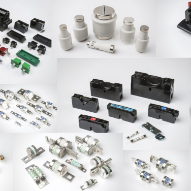
This guide takes each parameter in turn, explains what it means physically, and shows you how to apply it to real selection decisions — whether you are specifying a BS88 industrial fuse for a motor control centre, a gPV solar DC fuse for a photovoltaic combiner box, an HRC fuse for a transformer primary, or a miniature fuse for an electronics enclosure.
2. The Seven Parameters of Fuse Selection
Before working through each in detail, here is the complete list of parameters every fuse selection must address:
| # | Parameter | What it defines | Key question |
| 1 | Rated Current (In) | The continuous current the fuse can carry without operating | Is this fuse rated for the circuit’s design current? |
| 2 | Rated Voltage (Un) | The maximum voltage the fuse can safely interrupt | Is this fuse rated for the circuit voltage? |
| 3 | Breaking Capacity (Icu) | The maximum fault current the fuse can safely interrupt | Can this fuse handle the worst-case fault current at this point? |
| 4 | Utilisation Category | The type of circuit and load the fuse is designed for | Is this fuse the right type for this load (gG, gM, aM, gPV, aR)? |
| 5 | Physical Format | The physical size, fixing centres, and contact type | Will this fuse fit the holder and panel? |
| 6 | Time-Current Characteristics | How the fuse operates at different overcurrent magnitudes | Does this fuse’s operating speed suit the load and cable? |
| 7 | Coordination | How this fuse interacts with upstream and downstream protection | Does this fuse discriminate correctly with the rest of the protection system? |
Work through these in order. Many fuse selection errors stem from jumping straight to parameter 1 (current rating) without considering parameters 2 through 7 — any one of which can render an otherwise correctly-rated fuse unsuitable for the application.
3. Step 1 — Rated Current (In)
The rated current of a fuse is the maximum continuous current it can carry indefinitely without operating, at a defined ambient temperature (typically 20°C or 30°C for industrial fuses).
The Basic Rule
The rated current of the fuse must be greater than or equal to the design current of the circuit it protects:
In ≥ Ib (design current of the circuit)
And the rated current must be less than or equal to the current-carrying capacity of the cable it protects:
In ≤ Iz (current-carrying capacity of the cable)
This gives the fundamental constraint for fuse current rating selection:
Ib ≤ In ≤ Iz
The Conventional Circuit Protection Rule
For fuses protecting cables against overload under BS 7671 (IEE Wiring Regulations), there is an additional constraint: the fuse’s effective operating current at 1 hour (I₂) must not exceed 1.45 × Iz:
I₂ ≤ 1.45 × Iz
For BS 88 type gG fuses, I₂ is typically approximately 1.6 × In. This means that a gG fuse selected at or slightly above the cable’s current-carrying capacity will satisfy this constraint in most practical cases.
Ambient Temperature Derating
Fuse rated currents are specified at a reference ambient temperature — typically 20°C to 30°C for industrial fuse-links. In higher ambient temperatures, the fuse carries less current than its nominal rating without operating. Manufacturer derating curves provide correction factors for elevated ambient temperatures.
For industrial installations in hot environments — motor rooms, boiler houses, external enclosures in warm climates — always check the ambient temperature derating before confirming the current rating selection.
Motor Circuits — Watch for Starting Current
For motor circuit fusing, the starting inrush current of the motor must be considered. A direct-on-line (DOL) motor starter draws a starting current of typically 6 to 8 times the motor’s full-load current (FLC) for a duration of several seconds. A standard gG fuse selected on the motor’s FLC alone will often operate during motor starting — which is a nuisance trip, not a genuine fault.
This is why motor circuit protection uses a gM fuse (general purpose motor protection) or aM fuse (motor starting) rather than a standard gG fuse — a distinction covered in detail in Step 4.
4. Step 2 — Rated Voltage (Un)
The rated voltage of a fuse is the maximum system voltage at which the fuse can safely interrupt a fault current. Selecting a fuse with an inadequate voltage rating is a serious safety hazard — a fuse that cannot safely interrupt an arc at the actual system voltage may sustain a prolonged arc after operation, leading to fire, explosion, or equipment destruction.
AC vs DC Voltage Ratings
Most industrial fuses carry both an AC voltage rating and, where applicable, a DC voltage rating. DC voltage ratings are nearly always lower than the equivalent AC rating for the same fuse design, because DC arc extinction is significantly more demanding than AC (there is no natural current zero-crossing to aid arc suppression in a DC circuit).
For example, a BS88 industrial fuse rated at 415V AC may be rated for only 250V DC. A solar DC fuse application at 1000V DC requires a fuse specifically rated and certified for 1000V DC — not simply a fuse with an AC rating of 1000V.
Common Voltage Ratings in UK and International Installations
| Application | Typical System Voltage | Required Fuse Voltage Rating |
| UK single-phase domestic | 230/240V AC | ≥ 240V AC |
| UK three-phase industrial | 400/415V AC | ≥ 415V AC |
| European three-phase industrial | 400V AC | ≥ 400V AC |
| Higher-voltage industrial | 690V AC | ≥ 690V AC |
| UK electricity distribution | 415V AC | ≥ 415V AC |
| Solar PV (standard) | 1000V DC | ≥ 1000V DC |
| Solar PV (high voltage) | 1500V DC | ≥ 1500V DC |
| Telecommunications exchange | 50V DC | ≥ 50V DC |
Rule: Always select a fuse with a rated voltage equal to or greater than the highest voltage that can appear across the fuse under any operating or fault condition — including transients and open-circuit voltages (particularly relevant in solar PV systems where Voc under low temperature conditions can significantly exceed the standard Voc at STC).
5. Step 3 — Breaking Capacity (Icu)
Breaking capacity — also called rupturing capacity or making capacity — is the maximum prospective fault current (in kA rms) that the fuse can safely interrupt without risk of catastrophic failure. It is one of the most safety-critical parameters in fuse selection and one of the most frequently overlooked.
Why Breaking Capacity Matters
At the point of installation in an electrical system, the prospective short-circuit current (PSCC) — the maximum fault current that could flow if a dead short circuit occurred at that point — is determined by the supply impedance at that location. Close to a large supply transformer or a high-capacity busbar, PSCC values can be very high. Further from the supply, cable impedance reduces the PSCC.
If a fault occurs and the prospective fault current at the point of the fuse exceeds the fuse’s breaking capacity, the fuse may:
- Fail to interrupt the fault current at all
- Explode or shatter, releasing hot conducting material
- Sustain a prolonged arc capable of igniting surrounding materials
- Damage or destroy the fuse holder and adjacent equipment
None of these outcomes are acceptable. The fuse’s breaking capacity must always exceed the prospective fault current at the point of installation.
Typical Breaking Capacities by Fuse Type
| Fuse Type | Typical Breaking Capacity |
| BS88 Type N&T industrial (gG/gM) | 80kA AC at 415V |
| BS88 Type SS (690V) | 80kA AC at 690V |
| NH knife blade fuse (Type LSPN/DIN) | 120kA AC at 500V |
| General purpose Type MD (cylindrical) | 80kA AC at 415V |
| Solar DC fuse LFPV-32 | 20kA DC at 1000V DC |
| House service fuse Type ME/MF | 80kA AC at 415V (ASTA Certified) |
| Consumer unit fuse Type L | 16.5kA AC at 240V |
| Plug fuse Type PL (BS1362) | 6kA AC at 240V |
| Miniature fuse IEC 60127 (Type MIN) | Varies: typically 35A–1500A |
How to Find the Prospective Fault Current
For an existing installation, the PSCC at any distribution point can be measured using a prospective fault current meter. For a new installation design, PSCC is calculated from the supply transformer impedance (available from the DNO) and the impedance of the cables between the supply point and the point of protection.
In UK practice, the supply network prospective fault current at a typical low-voltage distribution board is often in the range of 6kA to 16kA for domestic installations and up to 50kA or higher for industrial installations close to large supply transformers.
Rule: Never assume that a lower breaking capacity fuse is safe because “the fault current here won’t be that high.” Always calculate or measure the PSCC and confirm it is below the fuse’s rated breaking capacity. If in doubt, specify a fuse with a higher breaking capacity.
6. Step 4 — Utilisation Category (gG, gM, aM, gPV, aR)
Utilisation category defines the type of circuit and load the fuse is designed to protect — and critically, the time-current operating characteristic it provides. Selecting the wrong utilisation category is one of the most common fuse selection errors.
The category is defined in IEC 60269 and BS 88 standards and consists of two parts: a letter indicating the breaking range, and a letter indicating the application.
Breaking Range — First Letter
- g — Full-range breaking capacity. The fuse can interrupt any current from the minimum fusing current up to its rated breaking capacity. This is the standard for most general purpose applications.
- a — Partial-range breaking capacity. The fuse can only interrupt currents above a defined multiple of the rated current (typically above approximately 3 × In). At lower overcurrents, the fuse does not operate — an upstream device must provide overload protection. aM and aR fuses are partial-range types.
Application — Second Letter
- G — General purpose cable and conductor protection
- M — Motor circuit protection (combined overload and starting current tolerance)
- R — Semiconductor protection (extremely fast-acting, very low I²t)
- PV — Photovoltaic solar system protection
The Key Utilisation Categories Explained
gG — General Purpose, Full Range The standard fuse for cable and conductor protection in the vast majority of industrial and commercial electrical applications. A gG fuse provides full-range protection against both overload and short-circuit currents. It is the correct choice for distribution circuits, sub-circuit fusing, transformer protection, and general electrical distribution where motor starting current is not a consideration.
gM — Motor Circuit Protection, Full Range A gM fuse has a dual rating: a lower continuous current rating (matching the motor’s full-load current) and a higher motor starting rating (allowing the fuse to tolerate the starting inrush current without nuisance tripping). A gM fuse rated NIT20M25 carries 20A continuously but tolerates a 25A starting current. gM fuses provide full-range protection including overload.
aM — Motor Starting, Partial Range An aM fuse is specifically designed for motor starting applications where a separate overload relay provides overload protection. The aM fuse only operates on short-circuit currents (above approximately 3 × In) — it does not provide overload protection in its own right. aM fuses are typically specified when a thermal overload relay is used in the starter and the fuse’s only role is short-circuit back-up protection.
gPV — Photovoltaic, Full Range As covered in the Solar DC Fuse guide, a gPV fuse is certified to IEC 60269-6 specifically for photovoltaic string array protection. It provides full-range protection including the low overcurrents (approximately 1.35–1.5 × Isc) associated with PV reverse current and multi-array faults. Never use a gG or aM fuse in a solar DC application — only a gPV fuse provides the correct PV-specific protection characteristics.
aR — Semiconductor Protection, Partial Range An aR fuse is an extremely fast-acting partial-range fuse designed to protect semiconductor devices (thyristors, IGBTs, diodes, rectifiers) that can be destroyed almost instantaneously by overcurrents that would merely be irritants to a standard fuse. The aR fuse operates within microseconds to limit the let-through energy (I²t) to a level the semiconductor device can survive. aR fuses do not provide overload protection — a gG fuse or relay must provide backup overload protection for the circuit.
Summary Table
| Category | Full/Partial Range | Typical Application | Provides Overload Protection? |
| gG | Full | General cable & conductor protection | Yes |
| gM | Full | Motor circuits with combined protection | Yes |
| aM | Partial | Motor starting (with separate overload relay) | No |
| gPV | Full | Solar PV string protection | Yes |
| aR | Partial | Semiconductor device protection | No |
| aG | Full | General purpose (AC and DC) | Yes |
7. Step 5 — Physical Format and Fixing Centres
Once the electrical parameters are confirmed, the physical format of the fuse must match the fuse holder, distribution equipment, or panel in which it is to be installed.
BS88 Bolted Tag Fuses — Fixing Centres
BS88 bolted-tag industrial fuse-links are defined by their fixing centres — the distance between the two contact tag bolt holes. The fixing centre must match the contact spacing of the fuse holder or distribution equipment exactly.
| BS88 Size | Series | Fixing Centre G1 | Current Range |
| A1 | NIT | 44.5mm (1¾”) | 2A–32A |
| A2 | TIA | 73mm (2⅞”) | 2A–32A |
| A3 | TIS | 73mm (2⅞”) | 35A–125A |
| A4 | TCP / TFP | 94mm (3 11/16″) | 6A–200A |
| B1 | TC / TBC | 111mm (4⅜”) | 2A–100A |
| B2 | TF / CTF | 111mm (4⅜”) | 125A–200A |
| B3 | TKF | 111mm (4⅜”) | 250A–315A |
| B4 | TMF | 111mm (4⅜”) | 355A–400A |
| C1 | TM | 133mm (5¼”) | 355A–400A |
| C2 | TTM | 133mm (5¼”) | 450A–630A |
| C3 | TLM | 133mm (5¼”) | 670A–800A |
Never mix BS88 sizes. A BS88 A2 fuse will not fit correctly in an A3 holder and may fail to make reliable contact — even where the physical body appears similar.
NH Knife Blade Fuses — NH Size
NH industrial fuse-links (knife blade fuses) are defined by their NH size — which determines the physical body dimensions and blade contact size.
| NH Size | Current Range | Typical Application |
| 000 | Up to 63A | Sub-circuit, control circuit |
| 00 | Up to 160A | Sub-circuit and feeder |
| 1 | Up to 250A | Sub-main distribution |
| 2 | Up to 400A | Main distribution |
| 3 | Up to 630A | Main incomer |
Cylindrical Fuses — Body Dimensions
Cylindrical fuses are defined by their diameter × length in mm. The most common industrial cylindrical formats are:
| Format | Typical Current Range | Application |
| 8.5 × 31.5mm | Up to 20A | Low-current sub-circuits |
| 10 × 38mm | Up to 32A | Industrial sub-circuits, solar PV strings |
| 14 × 51mm | Up to 50A | Mid-range industrial circuits |
| 22 × 58mm | Up to 125A | High-current distribution |
Miniature Fuses (IEC 60127)
| Format | Diameter × Length | Application |
| Miniature Fuse 5×20 | 5mm × 20mm | Electronics, consumer products (international standard) |
| Miniature Fuse 5×25 | 5mm × 25mm | UK-manufactured electronic equipment |
| Miniature Fuse 6.2×32 | 6.3mm × 32mm | Higher-current electronics and instrumentation |
8. Step 6 — Time-Current Characteristics
The time-current characteristic (also called the TCC, melting characteristic, or I-t curve) defines how long a fuse takes to operate at any given multiple of its rated current. Understanding the TCC is essential for ensuring the fuse will operate correctly under overload conditions without nuisance-tripping under normal load transients.
Reading a Time-Current Curve
A time-current curve plots operating time (seconds) on the vertical axis against prospective current (multiples of In, or kA) on the horizontal axis, typically on a log-log scale. The curve represents the fuse’s pre-arcing time — the time from the start of the overcurrent to the moment the fuse element melts and begins to arc.
Key points on the curve:
- Minimum fusing current — The lowest current at which the fuse will eventually operate (typically 1.25–1.45 × In for gG fuses). Below this, the fuse will never operate.
- Conventional fusing time — The time within which the fuse must operate at the conventional test current (typically 1.6 × In for gG fuses at 1 hour)
- Operating band — Between the minimum and maximum pre-arcing time curves, the fuse is guaranteed to operate within a defined band of times
Using the TCC for Cable Protection
For the fuse to provide effective cable protection against overload, the TCC must demonstrate that the fuse will operate before the cable’s conductor temperature reaches its maximum permitted temperature under overload conditions.
Under IEC 60364 and BS 7671, this is checked using the adiabatic equation:
t = (k × S)² / I²
Where:
- t = maximum permitted fault clearance time (seconds)
- k = conductor material factor (115 for 70°C PVC copper, 143 for 90°C XLPE copper)
- S = conductor cross-sectional area (mm²)
- I = fault current (A)
The fuse must clear the fault in less than time t for every possible fault current magnitude.
Using the TCC for Motor Circuit Coordination
For motor circuit fusing, the TCC must be assessed against the motor’s starting current profile to confirm there is no nuisance tripping risk. The starting current (typically 6–8 × FLC for DOL starting) must fall below the fuse’s minimum pre-arcing time at that current level for the duration of the starting time.
This is typically why gM or aM fuses are used for motor circuits rather than gG — their time-current characteristics are deliberately biased towards longer operating times at multiples of rated current corresponding to motor starting current, without compromising short-circuit protection at higher fault currents.
9. Step 7 — Fuse Coordination and Discrimination
Fuse coordination (also called selectivity or discrimination) is the practice of designing the fuse protection system so that, under any given fault condition, only the fuse immediately upstream of the fault operates — while all other fuses in the system remain intact and continue to supply healthy circuits.
Poor coordination — where a fault on a downstream sub-circuit causes an upstream fuse to blow as well — results in a far larger loss of supply than the fault warrants. In industrial plant, this can mean shutting down an entire production line when only a single machine circuit has faulted.
How Fuse Coordination Works
Fuse coordination relies on the difference in time-current characteristics between upstream (larger) and downstream (smaller) fuses. For the downstream fuse to operate first on a fault, its TCC must lie entirely to the left of (i.e. operate faster than) the upstream fuse’s minimum pre-arcing time curve at all fault current levels.
This is typically achieved by selecting upstream fuses with a significantly higher current rating than downstream fuses — the conventional rule of thumb is a current rating ratio of at least 1.6:1 between upstream and downstream fuses for reliable discrimination.
For high-performance discrimination (particularly where fault current levels are high), detailed comparison of the manufacturer’s TCC curves is essential. Many fuse manufacturers publish coordination tables showing which pairings of their fuses provide guaranteed discrimination at specified fault current levels.
Total Discrimination vs Back-up Protection
Two coordination strategies are commonly used:
Total discrimination: The downstream fuse always operates before the upstream fuse at all fault current levels. This is the preferred approach for critical circuits where loss of supply to healthy circuits must be avoided.
Back-up protection: The downstream fuse operates for lower-level faults, but for very high fault currents (often above the breaking capacity of the downstream fuse), the upstream fuse provides back-up interruption. This is acceptable where the downstream fuse’s breaking capacity is lower than the prospective fault current at its point of installation — the upstream fuse must be able to interrupt the fault even if the downstream fuse fails to do so completely.
Coordination with Other Protection Devices
Where fuses are used alongside circuit breakers, RCDs, or contactors in a protection scheme, the coordination between these devices must also be verified. In particular:
- A fuse used as a back-up for a circuit breaker must have a breaking capacity sufficient to interrupt the prospective fault current if the circuit breaker fails to clear it
- The fuse’s I²t let-through energy at the highest prospective fault current must be within the withstand capability of the downstream circuit breaker, contactor, or other device being protected
10. Fuse vs Circuit Breaker — Which Should You Use?
This is one of the most frequently asked questions in protection system design. Both fuses and circuit breakers interrupt overcurrent faults, but they do so in fundamentally different ways with different characteristics.
Advantages of Fuses
Higher breaking capacity: HRC fuses routinely achieve 80kA to 120kA breaking capacity in compact formats. Equivalent MCBs and MCCBs with the same breaking capacity are significantly larger and more expensive.
Lower let-through energy (I²t): A fuse limits the let-through energy during a fault far more effectively than a circuit breaker, because it begins to limit current before the fault current reaches its prospective peak. This current-limiting action protects downstream equipment from the electrodynamic forces of high fault currents.
No moving parts — no mechanical failure: A fuse has no mechanical mechanism to fail. A circuit breaker has springs, contacts, latches, and actuators that can fail to operate correctly, particularly if not regularly tested.
Lower cost at high ratings: For high current ratings (above 200A) and high breaking capacity requirements, HRC fuses are generally significantly less expensive than equivalent circuit breakers.
Inherent reliability: A correctly-rated and correctly-installed fuse will operate on a fault with absolute certainty. It cannot be accidentally left in an open or incorrectly reset position.
Advantages of Circuit Breakers
Re-closable: A circuit breaker can be reset after a trip — no replacement component is needed. For circuits that experience frequent nuisance trips (particularly in motor starting applications), this can significantly reduce maintenance time and cost.
Visual indication: Most circuit breakers provide clear visual indication of a tripped state. A blown fuse requires visual inspection or testing to identify.
Adjustable settings: Some circuit breakers (particularly MCCBs) allow adjustment of the overload and short-circuit trip thresholds, making them more flexible for applications where the load characteristics may change.
Isolation function: A circuit breaker can be used as both a protective device and an isolator, reducing the number of devices required in the circuit.
When to Choose a Fuse
- Where very high breaking capacity is required in a compact form factor
- Where the protection system benefits from high current-limiting performance (protection of sensitive downstream equipment)
- Where total life-cycle cost favours fuses (high-current industrial distribution)
- Where the fault occurs rarely and routine replacement is acceptable
- For semiconductor protection (aR fuses have no circuit breaker equivalent)
- For solar DC string protection (gPV fuses have no circuit breaker equivalent)
When to Choose a Circuit Breaker
- Where frequent operation is expected (motor circuits with regular starts/stops)
- Where remote or automated reset is needed
- Where the isolating function of the circuit breaker reduces installed equipment cost
- For domestic consumer units and small commercial premises where convenience and RCD integration are priorities
In many industrial installations, the optimum solution uses both: HRC fuses for the main distribution and high-fault-level sections of the system, and circuit breakers for final sub-circuits and motor starters.
11. Common Fuse Selection Mistakes and How to Avoid Them
Mistake 1: Selecting on Current Rating Alone
The most common mistake. Engineers select a fuse that matches the circuit’s design current and stop there — without checking breaking capacity, voltage rating, or utilisation category. A fuse selected purely on current rating may be inadequate on any or all of the remaining parameters.
Fix: Always work through all seven selection parameters before confirming the fuse specification.
Mistake 2: Insufficient Breaking Capacity
Installing a fuse with a breaking capacity below the prospective fault current at the point of installation. This is particularly common in industrial installations close to large supply transformers, where PSCC can exceed 50kA.
Fix: Always calculate or measure the PSCC at the point of installation before specifying the fuse. For industrial distribution, the Lawson Type N&T BS88 fuse range offers 80kA breaking capacity across the full current range — providing a generous safety margin for most UK industrial applications.
Mistake 3: Wrong Utilisation Category for Motor Circuits
Installing a gG general purpose fuse in a motor starting application without checking whether the starting inrush current will cause nuisance operation. A motor drawing 6 × FLC for 5 seconds on starting may cause a correctly-rated gG fuse to operate — not because there is a fault, but because the gG characteristic is not designed for motor starting duty.
Fix: For motor circuit fusing, specify a gM fuse (for combined overload and short-circuit protection) or an aM fuse (for back-up short-circuit protection alongside a thermal overload relay).
Mistake 4: Using AC-Rated Fuses in DC Circuits
Installing a fuse with only an AC voltage rating in a DC circuit. DC fuses have significantly lower voltage ratings than their AC equivalents because DC arc extinction is more demanding. A fuse rated 415V AC may be rated for only 250V DC — and a solar DC application at 1000V DC requires a specifically 1000V DC-rated gPV fuse.
Fix: Always check both AC and DC voltage ratings. For DC applications, verify the fuse’s DC voltage rating explicitly — do not assume it equals or approximates the AC rating.
Mistake 5: Oversizing to Prevent Nuisance Tripping
When a fuse keeps blowing, the instinctive response of some engineers is to fit a higher-rated fuse. This is dangerous. A fuse that keeps blowing is telling you something — there is an overload, intermittent fault, or incorrect selection in the circuit. Fitting a higher-rated fuse may prevent the nuisance trips, but it removes the overcurrent protection from the circuit, potentially allowing a cable fire or equipment destruction in the event of a genuine sustained fault.
Fix: Investigate the root cause of nuisance tripping (see Section 12 below) rather than oversizing the fuse.
Mistake 6: Ignoring Coordination
Installing replacement fuses of the same current rating as the originals without checking whether the coordination with upstream and downstream protection is maintained. This is common during maintenance when like-for-like replacement is assumed to be automatically safe.
Fix: When replacing fuses, always confirm the fuse type and rating against the original design specification. If the original fuse type is unavailable, verify that the replacement has equivalent TCC characteristics before installation.
12. Why Does My Fuse Keep Blowing?
A fuse that repeatedly operates on the same circuit is communicating a fault or design issue — not a defective fuse. Here are the seven most common causes:
1. Genuine Overload
The circuit is carrying more current than it was designed for. This can occur where additional equipment has been connected to a circuit, where a motor is mechanically overloaded, or where the ambient temperature has increased. Solution: Identify and reduce the load, or redesign the circuit for the actual load.
2. Motor Starting Current
A gG fuse in a motor circuit is operating on the starting inrush current rather than a genuine fault. Solution: Replace the gG fuse with a correctly-rated gM or aM fuse for the motor circuit application.
3. Transformer Inrush Current
Transformers produce a large magnetising inrush current when energised — typically 8–12 × the transformer’s rated current for the first few cycles. A standard gG fuse selected for the transformer’s full-load current may operate on energisation. Solution: Select a fuse with a time-current characteristic that can tolerate the inrush duration, or specify a fuse with a sufficient rating margin.
4. Intermittent Earth Fault or Short Circuit
A recurring intermittent fault — for example, a cable with damaged insulation that arcs to earth intermittently — will cause periodic fuse operation. The fuse is functioning correctly; the fault is in the circuit. Solution: Conduct insulation resistance testing and cable inspection to locate and rectify the fault.
5. Incorrect Current Rating Selection
The fuse has been selected at too low a current rating relative to the actual circuit design current. Solution: Recalculate the correct fuse rating using the methodology in this guide.
6. Harmonic Currents
In circuits supplying variable speed drives, UPS systems, or large numbers of switched-mode power supplies, the total RMS current drawn by the circuit — including harmonic components — can significantly exceed the fundamental current. A fuse correctly rated for the fundamental current may operate on the elevated RMS total current. Solution: Conduct harmonic current analysis and derate the fuse accordingly, or address the source of harmonic distortion.
7. Ambient Temperature
In high ambient temperatures, fuse current-carrying capacity is derated. A fuse that performs correctly in a 25°C panel may operate below its nameplate current in a 50°C environment. Solution: Apply the manufacturer’s temperature derating factors and reselect the fuse rating for the actual installation temperature.
13. Quick-Reference Fuse Selection Checklist
Use this checklist for every fuse selection before confirming the specification:
Electrical Parameters
- Rated current In ≥ design current Ib of circuit
- Rated current In ≤ cable current-carrying capacity Iz
- Rated voltage Un ≥ maximum system voltage (AC and/or DC as applicable)
- Breaking capacity Icu ≥ prospective short-circuit current at point of installation
- Utilisation category confirmed: gG / gM / aM / gPV / aR as appropriate for load type
- Time-current characteristic suits the load (motor starting, transformer inrush, semiconductor, etc.)
- Fuse coordinates with upstream and downstream protection devices
Physical Parameters
- Fuse format matches the holder: BS88 fixing centres / NH size / cylindrical dimensions confirmed
- Fuse holder rated for the same voltage and current as the fuse
- Fuse holder breaking capacity ≥ PSCC (for bolted-type holders)
- Environmental rating of holder suits installation environment (IP, temperature, altitude)
Compliance & Quality
- Fuse certified to applicable standard: IEC 60269-1, -2, -3, -4, or -6 as appropriate
- ASTA Certified where specified
- Manufacturer ISO 9001 accredited
- Product traceability confirmed for critical or safety-critical applications
14. Frequently Asked Questions
Q: What is the difference between a fuse and a circuit breaker?
A fuse is a single-use protective device that interrupts a circuit by melting its internal element when overcurrent occurs. A circuit breaker is a re-usable mechanical switching device that trips under overcurrent conditions and can be reset. Fuses generally offer higher breaking capacities and lower I²t let-through energy in compact formats; circuit breakers offer the advantage of resettability and no component replacement after operation.
Q: What does In mean on a fuse?
In is the rated current of the fuse — the maximum continuous current the fuse can carry at its specified reference ambient temperature without operating. For example, an NIT 32 fuse has a rated current (In) of 32A.
Q: What is breaking capacity and why does it matter?
Breaking capacity is the maximum fault current a fuse can safely interrupt. If the prospective fault current at the point of installation exceeds the fuse’s breaking capacity, the fuse may fail catastrophically during a fault — potentially causing arc flash, fire, or explosion. Breaking capacity must always be verified against the calculated or measured PSCC at the installation point.
Q: What is the difference between gG and gM fuses?
A gG fuse is a general purpose fuse providing full-range protection for cable and conductor protection. A gM fuse is a motor circuit protection fuse with a dual current rating — a continuous rating matching the motor FLC and a higher motor starting rating — designed to tolerate the starting inrush of a DOL or star-delta motor without nuisance tripping while still providing full overload and short-circuit protection.
Q: Can I replace an aM fuse with a gG fuse of the same current rating?
No — not without careful analysis. An aM fuse only provides short-circuit protection (partial range); overload protection is provided by a separate thermal overload relay in the motor starter. Replacing an aM fuse with a gG fuse of the same current rating may result in nuisance operation on motor starting inrush, because the gG’s time-current characteristic does not tolerate the starting current that the aM is designed to pass through. If replacing aM with gG, the circuit coordination must be re-evaluated.
Q: How do I find the prospective fault current at a distribution point?
For existing installations, use a prospective short-circuit current (PSCC) meter measured at the distribution board terminals with the supply connected. For new installations, calculate using the supply transformer impedance (available from the DNO or switchgear supplier) and the cable impedances between supply and distribution point. Many electrical design software packages (Amtech, Trimble, Hevacomp) calculate PSCC automatically as part of the circuit design process.
Q: How do I know if my fuses are correctly coordinated?
Compare the time-current characteristic curves of the upstream and downstream fuses across the range of possible fault currents. For the downstream fuse to discriminate, its maximum pre-arcing time must be less than the upstream fuse’s minimum pre-arcing time at all fault current magnitudes. Manufacturer coordination tables simplify this for common fuse pairings. At a minimum, ensure a current rating ratio of at least 1.6:1 between upstream and downstream fuses.
Q: What is a nuisance trip and how do I prevent it?
A nuisance trip occurs when a fuse operates in the absence of a genuine fault — typically caused by transient overcurrents from motor starting, transformer energisation, or capacitor switching. Prevention involves: selecting the correct utilisation category (gM or aM for motor circuits), ensuring the fuse’s TCC accommodates the expected load transients, and verifying the ambient temperature derating has been applied correctly.
Summary — The Seven Steps of Fuse Selection
Correct fuse selection is a seven-step process that must be completed in sequence for every application:
- Rated current (In): In must be ≥ Ib and ≤ Iz, with adjustment for ambient temperature
- Rated voltage (Un): Un must equal or exceed the maximum system voltage — including DC voltages separately
- Breaking capacity (Icu): Icu must exceed the prospective fault current at the point of installation
- Utilisation category: gG for general circuits; gM or aM for motors; gPV for solar; aR for semiconductors
- Physical format: Fixing centres, NH size, or cylindrical dimensions must match the holder exactly
- Time-current characteristics: TCC must suit the load and provide cable protection within the required time
- Coordination: Downstream fuse must operate before upstream fuse for any fault on the downstream circuit
About Lawson Fuses
Lawson Fuses is a UK-based manufacturer of high-quality fuse-links and fuse holders, part of the Lucy Group. Established in 1938, Lawson designs and manufactures certified fuse-links across every major international fuse standard — from BS88 industrial fuse-links and NH knife blade fuses to solar DC fuses, semiconductor protection fuses, and household consumer fuses.
All Lawson products are manufactured under an ISO 9001 accredited quality management system with test facilities independently accredited to ISO/IEC 17025, and are ASTA Certified under the ASTA 20 Authorisation Scheme.